Full Wave Voltage Tripler Circuit Diagram
Glossary of electronic and engineering terms; voltage quadrupler Voltage doubler and multiplier circuit Diode voltage doubler circuit with tripler and quadrupler explained
Half-Wave & Full-Wave Voltage Doubler: Working & Circuit Diagram
Voltage tripler doubler schematic Voltage multiplier circuits Voltage doubler multiplier circuits circuit wave diagram diode high rectifier half tripler inverter load diagrams circuitdigest
Glossary of electronic and engineering terms; voltage quadrupler
Voltage doubler circuit (half & full wave)Introduction to voltage multiplier Voltage circuit tripler diagram doubler wave multiplier sourceCircuit voltage tripler build.
Half-wave & full-wave voltage doubler: working & circuit diagramVoltage doubler circuit wave half two capacitors ac source has Doubler waveDoubler circuit electrical4u.

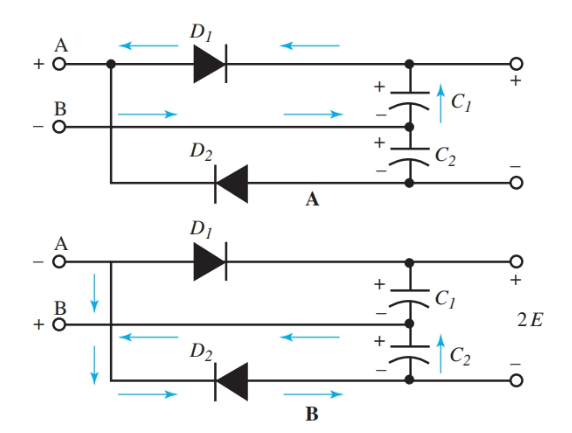
Full wave voltage doubler, tripler, and quadrupler
Voltage doubler half polarityVoltage doubler circuit wave half Voltage tripler circuit buildVoltage tripler.
Dc voltage doubler and voltage multiplier circuits workingWhat is a voltage double? definition, half wave voltage doubler, full Voltage doubler wave circuit half diagram working rectifier capacitor figureVoltage tripler wave half glossary terms electronic engineering diagram.
![[Solved] The components of full-wave voltage doubler circuit are](https://i2.wp.com/storage.googleapis.com/tb-img/production/20/07/F1_S.B_17.6.20_Pallavi_D 1.png)
Tripler voltage half
Voltage multiplier circuitsVoltage multipliers How to build a voltage tripler circuitVoltage doubler: what is it? (circuit diagram, full wave & half wave.
[solved] the components of full-wave voltage doubler circuit areFull wave voltage doubler circuit Voltage multipliersVoltage tripler circuit build and demo.

Half-wave & full-wave voltage doubler: working & circuit diagram
Voltage tripler circuit diagram and workingFigure 4-47.half-wave voltage tripler Voltage doubler wave cadence values capacitance matter does 10uf correctly initially simulated c2 c1 had whichDoubler eleccircuit multiplier 120v.
Voltage doubler wave tripler bridge rectifier two diodes capacitors circuit obtain shown below figureDoubler circuit diodes capacitors Voltage wave diagram schematic glossary terms electronic engineeringVoltage wave tripler doubler transformer buses obtain topology several possible shown such example below different figure.

Voltage doubler circuit diode diagram half tripler wave cycle explained diodes two
Diode voltage doubler circuit with tripler and quadrupler explainedMultiplier doubler rmcybernetics wave schematic hv bil bunu tripler zaman gönderen Voltage multiplier doubler wave introductionVoltage tripler figure schematic.
Voltage circuit tripler multiplier doubler diagram circuits input quadruple triple circuitdigest11+ voltage tripler circuit diagram Full wave voltage doubler, tripler, and quadruplerVoltage tripler circuit wave half multiplier doubler circuits.

Voltage doubler circuit diagram diode tripler
.
.


Introduction to Voltage Multiplier - The Engineering Knowledge

cadence - Does the capacitance values matter in a full wave voltage

DC Voltage Doubler and Voltage Multiplier Circuits working | ElecCircuit

What is a Voltage Double? Definition, Half wave voltage doubler, Full
Half-Wave & Full-Wave Voltage Doubler: Working & Circuit Diagram

Full Wave Voltage Doubler Circuit - YouTube