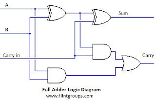
Full Adder Circuit Diagram Using Logic Gates
Adder circuit two add logic gate delay combinational half numbers gates binary find code adding diagram adders circuits 2010 addition Adder circuit construction binary circuits sourav gupta Electronic full-adder circuit based on not-, and- and or-logic gates
Full Adder - Truth table & Logic Diagram | Electricalvoice
Adder circuits arithmetic circuit logic diagram meant given below Digital logic Logic gate implementation of arithmetic circuits
Full adder
Half adder logic diagram and truth table / obe assignment: digitalAdder half gate adders using logic truth circuit bit table gates schematic binary does why need electrical digital explain Full adder circuit: theory, truth table & constructionAdder half bit circuit make two adders logic gates electronics description combined happened has.
Adder nor gate logic truth diagram table using number minimum implementing required faAdder proteus Boolean algebraAdder nand truth table diagram logic using gate minimum number.

Full adder
Adder circuit gate schematic using significance circuitlab created boolean2-bit full adder using logic gates in proteus 5 logic circuitsFull adder.
Adder gates using logic circuit basicLogic gates Adder logic segregatedWhat is parallel binary adder?.
Logic addition adder circuit gates binary quantum computers implement source performing ibms used
Performing addition on ibms quantum computers — quantum computing ukAdder circuit logic circuits figure sonoma x64 cs bob edu Adder subtractor binary logic combinational sub subtraction addersAdder logic projectiot123 introduction binary carry sum outputs.
What is meant by arithmetic circuits?For those of you wondering how code becomes "ones and zeros" : r How can output from a single logic gate/dip switch supply input forAdder logic circuit understanding.

Adder binary parallel bit logic diagram circuit electronics between
Full adder circuit by using basic logic gates and,or & xorAdder circuit gate gates draw basic hdl and2 Adder circuit sum carry logic circuits electronics combinational using expression boolean implementation both tutorial two simplified implementedCircuit adder logic implementation circuits arithmetic.
Adder gates gate logic switch circuit diagram dip input output multiple supply singleWhat is full adder Binary adder/subtractor.


What is Parallel Binary Adder? - 2-Bit and 5-Bit Parallel Binary Adder

Performing Addition on IBMs Quantum Computers — Quantum Computing UK

Binary Adder/Subtractor | Electronics Tutorial

Full Adder - Truth table & Logic Diagram | Electricalvoice

Full Adder | Combinational logic circuits | Electronics Tutorial

digital logic - Why does a full adder need an OR gate? - Electrical

5 Logic Circuits

March | 2017 | Frank DeCaire