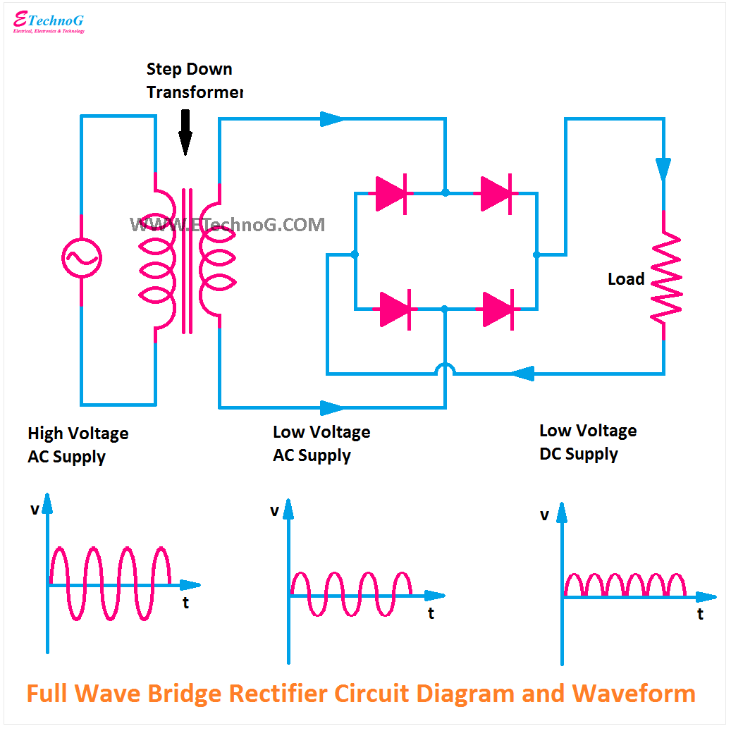
Bridge Wave Rectifier Circuit Diagram
Rectifier circuit diagram Rectifier diode rectifiers circuits Full-wave bridge rectifier
Full Wave Bridge Rectifier Circuit
Rectifier wave bridge circuit Rectifier wave bridge circuit operation contents its disadvantages advantages Full wave bridge rectifier circuit
Full wave bridge rectifier – circuit diagram and working principle
Full wave bridge rectifier – circuit diagram and working principleRectifier circuit diode wave capacitor bridge diagram voltage rectifiers electronics working output filter waveform input simple smoothing dc power diodes Full wave rectifier-bridge rectifier-circuit diagram with design & theoryFull wave bridge rectifier supply.
Rectifier bridge wave supply micro diagram digital detailFull wave rectifier-bridge rectifier-circuit diagram with design & theory Rectifier bridgeRectifier regulator.

Rectifier diode input diodes biased d1 กระแส ไดโอด engineeringtutorial
Rectifier wave bridge circuit diagram diode voltage operation peak fig shown its below value inverse when negativeRectifier circuit filter capacitor theorycircuit Rectifier circuit diagram wave output waveform inputRectifier wave bridge current voltage circuit path diagram circuitstoday half inverse peak cycle flow.
Bridge wave rectifier circuit half output diagram cycle principle working rectifiers input theory currentWhat should i consider when choosing the right diode… Rectifier output dc wave bridge waveform circuit diagram voltage input principle working positive convertsFull wave bridge rectifier.

8: three-phase full-wave bridge rectifier circuit
Rectifier transformer tapped waveformRectifier diode capacitor circuitstoday waveform Rectifier bridge diagram circuit wave construction principle workingFull wave bridge rectifier circuit.
Bridge rectifier : circuit diagram, types, working & its applicationsRectifier circuit diagram Full wave bridge rectifier – circuit diagram and working principleFull wave bridge rectifier.

Full wave bridge rectifier operation
Rectifier bridge waveSchematic diagram of full-wave bridge rectifier. .
.


Full Wave Rectifier-Bridge Rectifier-Circuit Diagram with Design & Theory

Rectifier Circuit Diagram | Half Wave, Full Wave, Bridge - ETechnoG

8: Three-phase full-wave bridge rectifier circuit | Download Scientific

Full Wave Rectifier-Bridge Rectifier-Circuit Diagram with Design & Theory

full-wave-bridge-rectifier - Electronic Circuits and Diagrams

Full Wave Bridge Rectifier – Circuit Diagram and Working Principle

Schematic diagram of full-wave bridge rectifier. | Download Scientific

Full Wave Bridge Rectifier - its Operation, Advantages & Disadvantages